Arduino Portenta X8
Note
The instructions in this section also applies to those boards with secure boot enabled. There are references on how to perform common instructions along with the flow.
Secure Boot (Hardware Root of Trust) details the required background for secure boot.
Preparation
Important
Ensure you replace <factory> With the name of your Factory.
Download the necessary files from
https://app.foundries.io/factories/<factory>/targetsClick the latest Target with the
platformTrigger.Expand the Runs section which corresponds with the board. Download the Factory image for that machine:
lmp-partner-arduino-image-<machine-name>.wic.gz
u-boot-<machine-name>.itb
sit-<machine-name>.bin
imx-boot-<machine-name>
Extract
lmp-partner-arduino-image-<machine-name>.wic.gz:gunzip lmp-partner-arduino-image-<machine-name>.wic.gzExpand the Runs section which corresponds with the board. Download the corresponding mfgtool files, e.g.,
mfgtool-files-<machine-name>.tar.gz.Extract the files:
tar -zxvf mfgtool-files-<machine-name>.tar.gz
Organize the files, mirroring the tree below:
├── lmp-partner-arduino-image-<machine-name>.wic
├── u-boot-<machine-name>.itb
├── sit-<machine-name>.bin
├── imx-boot-<machine-name>
└── mfgtool-files-<machine-name>
      ├── bootloader.uuu
      ├── full_image.uuu
      ├── imx-boot-mfgtool
      ├── uuu
      └── uuu.exe
Hardware Preparation
Set up the board for updating using the manufacturing tools:
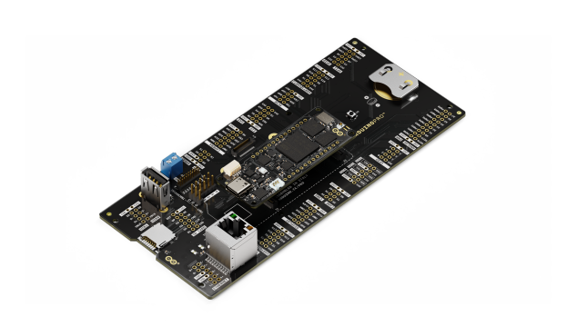
Fig. 42 portenta-x8
- OPTIONAL: Only required if you have problems and/or want to see the boot console output.
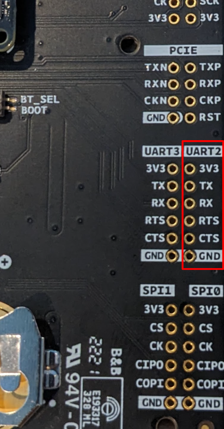
Fig. 43 UART 2 Pins
You may need to solder a six pin header to the UART2 pad.
Connect a TTL USB to UART 3v3 adapter to the corresponding UART 2 pins on the breakout board.
Connect the other end of the cable to a PC acting as a host terminal.
A UART connection will appear on the PC.
On a Linux® host for example:
$ ls -l /dev/serial/by-id/
total 0
lrwxrwxrwx 1 root root 13 Dec 18 11:09 usb-FTDI_TTL_RS232-if00-port0 -> ../../ttyUSB0
Using a serial terminal program like minicom, connect to the port with
if00in the name (in this example ttyUSB0) and apply the following configuration- Baud rate: 115200
- Data bits: 8
- Stop bit: 1
- Parity: None
- Flow control: None
Tip
If you are not receiving console output to swap the TX and RX pins. Most TTL USB to UART adaptors do not provide the cross over function.
Ensure that the power is off—no power input connected.
Put the Portenta x8 into programming mode:
Switch BT_SEL to ON and switch BOOT to ON as shown below.
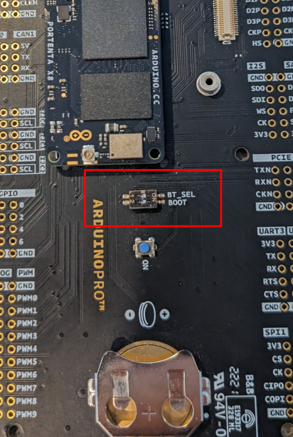
Fig. 44 BT_SEL and BOOT programming settings
Connect your computer to the Portenta X8 board via either USB-C® to USB-A or USB-C® to USB-C®. This connection will power your board ON. It is best to use 5V supply with at least 2A via a USB-C® connector. Negotiating power supplies do not always work and frequent reboots can be detected.
Flashing
Once in serial downloader mode and connected to your PC the evaluation board should show up as an NXP® USB device.
Note
For instructions on how to sign the required images before flashing them to the board with secure boot enabled, follow the instructions from Machines with Secure Aspects Enabled by FoundriesFactory.
Verify target is present:
$ lsusb | grep NXP
Bus 001 Device 023: ID 1fc9:012b NXP Semiconductors i.MX 8M Dual/8M QuadLite/8M Quad Serial Downloader
In this mode, you will use the
uuutools to program the images to the eMMC. TheUSB IDmay differ if a different SoC is used.To program the LmP to the EMMC, run:
$ sudo mfgtool-files-<machine-name>/uuu -pp 1 mfgtool-files-<machine-name>/full_image.uuu
uuu (Universal Update Utility) for nxp imx chips -- libuuu_1.4.43-0-ga9c099a

Success 1    Failure 0


1:31     3/ 3 [=================100%=================] SDPV: jump
2:31     8/ 8 [Done                                  ] FB: done
Turn off the power
Put the board into run mode.
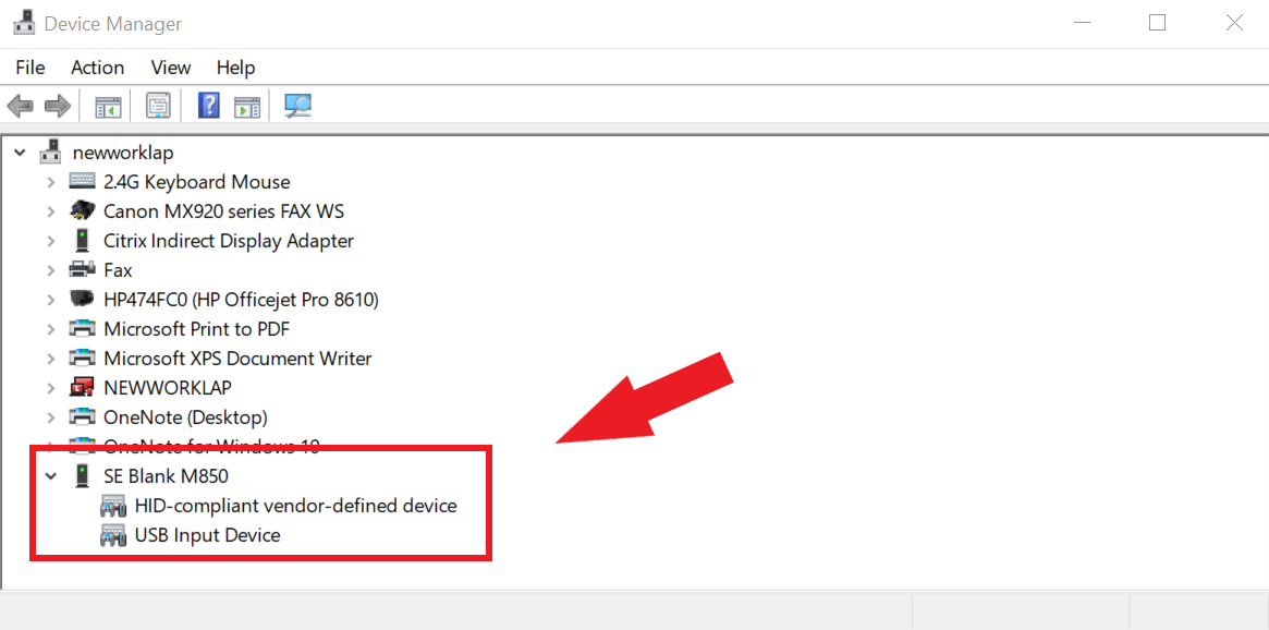
- Start the
Device Manager - Select
View - Select
Devices by container - Verify a device as in the following:
To program the LmP to the EMMC, run:
C:\Users\Someone> mfgtool-files-<machine-name>\uuu.exe -pp 1 mfgtool-files-<machine-name>\full_image.uuu
uuu (Universal Update Utility) for nxp imx chips -- libuuu_1.4.43-0-ga9c099a

Success 1    Failure 0


1:31     3/ 3 [=================100%=================] SDPV: jump
2:31     8/ 8 [Done                                  ] FB: done
Turn off the power
Put the board into run mode.
To put the Portenta X8 into run mode, switch BT_SEL and BOOT to OFF.