STM32MP15 EV1 Evaluation Board
This page shows how to flash an STM32MP15 EV1 board with LmP artifacts.
Getting Required Software
STM32CubeProgrammer is used to flash the STM32MP15 EV1 board. This section shows how to properly download and setup this tool on a Linux machine. Please skip to the next section if STM32CubeProgrammer is already installed on your machine.
- Download the STM32CubeProgrammer software for Linux.
- Unzip it to a known location:
mkdir <STM32CubeProgrammer_path>
unzip en.stm32cubeprg-lin_v*.zip -d <STM32CubeProgrammer_path>
- Run the installer and follow the instructions on screen:
./SetupSTM32CubeProgrammer*.linux
- Export the
STM32CubeProgrammer_pathto the system path:
export PATH=<STM32CubeProgrammer_path>/bin:$PATH
- To allow STM32CubeProgrammer to access the USB port through low-level commands, proceed as follows:
cd <STM32CubeProgrammer_path>/Drivers/rules
sudo cp *.* /etc/udev/rules.d/
- Download the STM32CubeProgrammer software for Windows.
- Unzip it to a known location.
- Execute the Windows installer and follow the instructions on screen.
- Run
STM32 Bootloader.batto install the required DFU drivers and activate the STM32 device in USB DFU mode.
For more information, check the STM32CubeProgrammer Installation page.
Preparation
On your factory, click on the latest
platform-develbuild: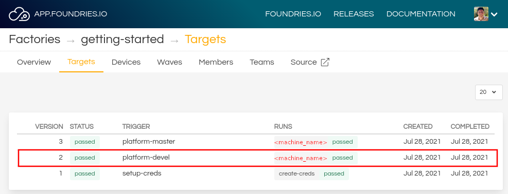
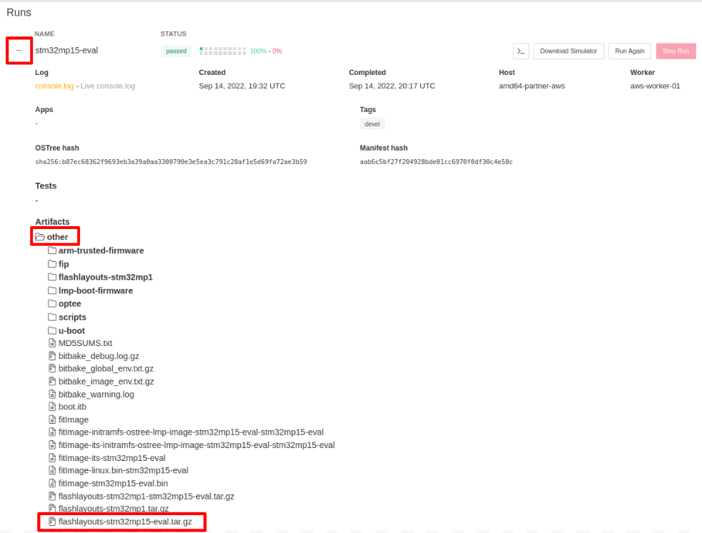
2. Expand the run for stm32mp15-eval and look for the flashlayouts-stm32mp15-eval.tar.gz
artifact under the other folder:
- Unzip the downloaded file:
tar -xvf flashlayouts-stm32mp15-eval.tar.gz
The file used for flashing is FlashLayout_stm32mp1-optee.tsv.
Hardware Preparation
Connect the USB OTG cable in the base board to the host machine.
Set the boot switches in the CPU board to Serial Download Mode,
0000: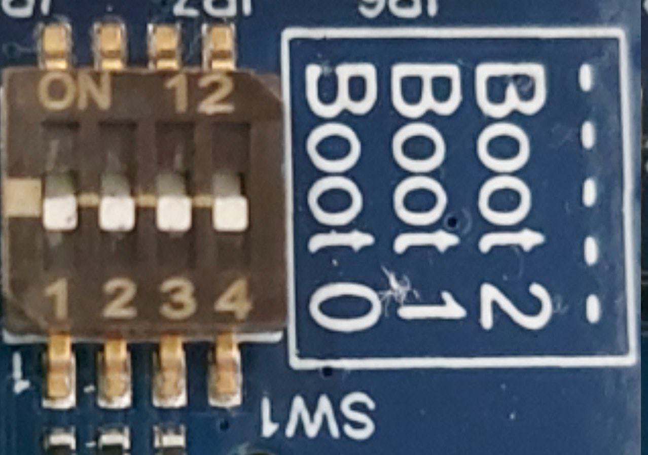
Fig. 91 stm32mp15-ev1 SDP mode
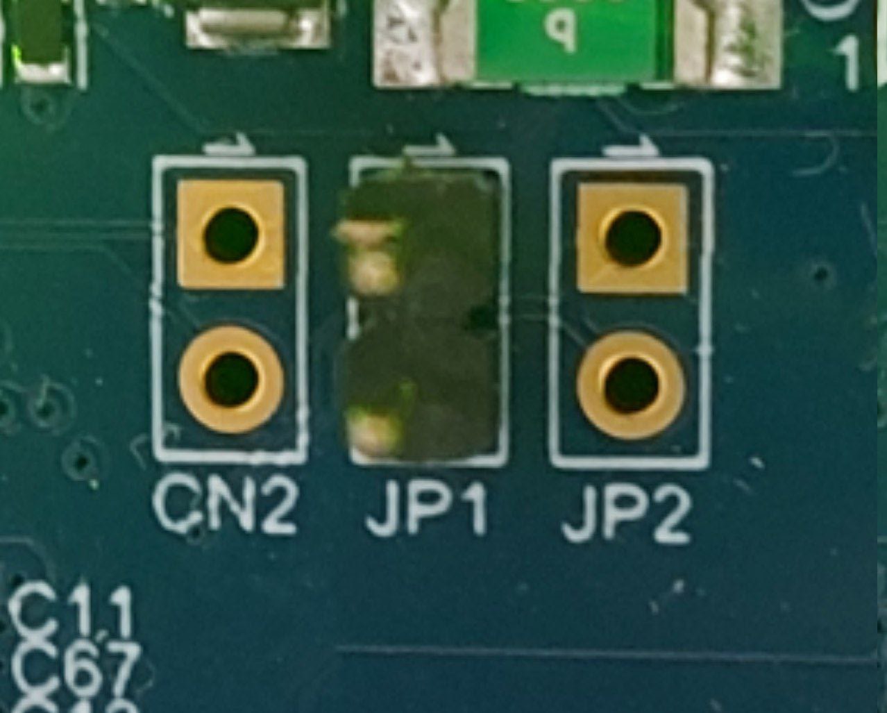
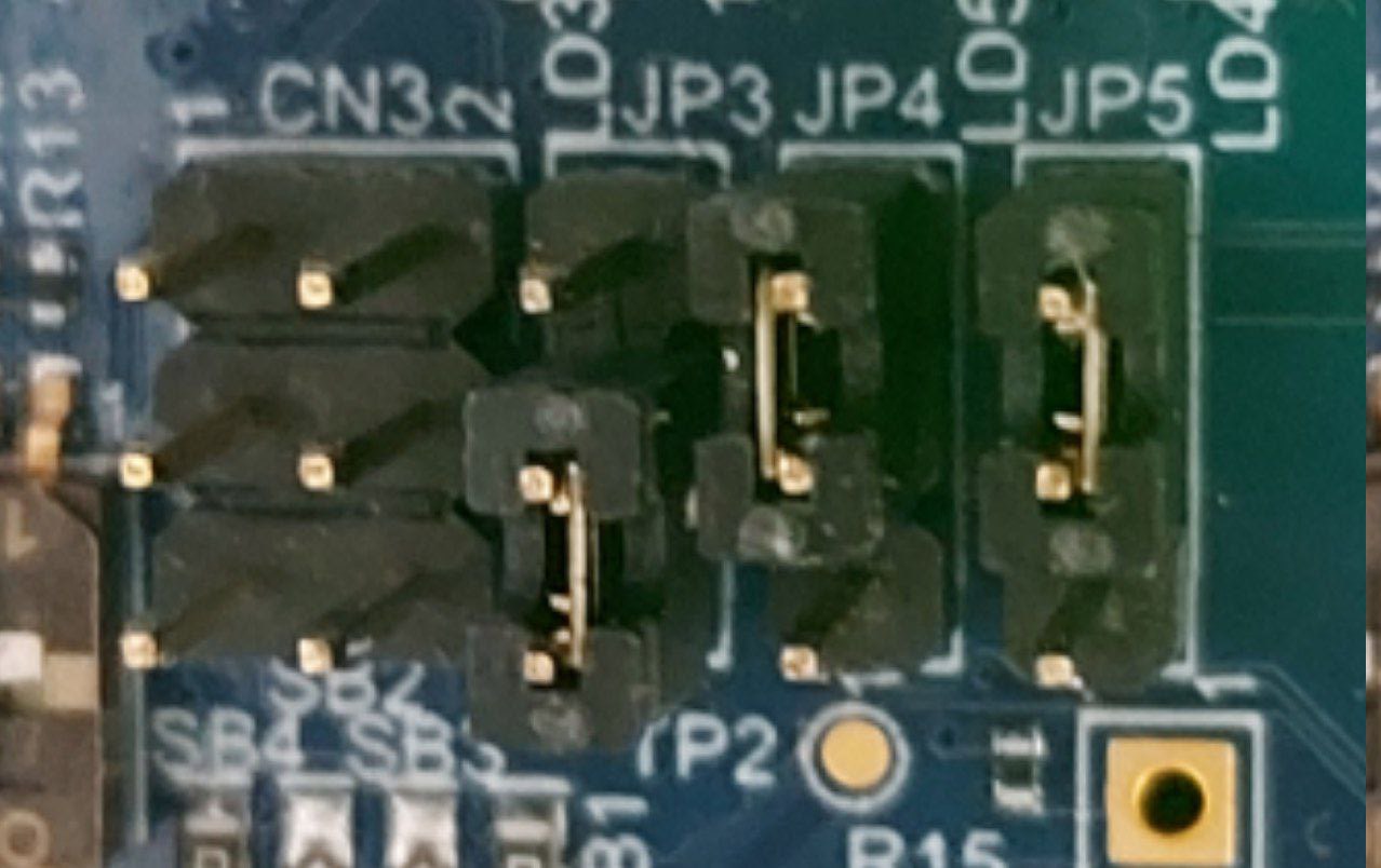
3. OPTIONAL: For UART output in the USB connector in the CPU board, remove
JP1 jumper and move JP4 and JP5 to the 2-3 position, as pictures
below:
Flashing
- Turn on the board and verify that it is set for serial download mode:
STM32_Programmer_CLI -l usb
     -------------------------------------------------------------------
                       STM32CubeProgrammer v2.11.0
     -------------------------------------------------------------------

=====  DFU Interface   =====

Total number of available STM32 device in DFU mode: 1

 Device Index           : USB1
 USB Bus Number         : 001
 USB Address Number     : 001
 Product ID             : DFU in HS Mode @Device ID /0x500, @Revision ID /0x0000
 Serial number          : 002B00323438511836383238
 Firmware version       : 0x0110
2. Flash the board. Make sure to replace the command below with the USB Device
Index from the previous step if needed:
STM32_Programmer_CLI -c port=usb1 -w FlashLayout_stm32mp1-optee.tsv
This can take a few minutes to complete. The process can be watched from the host console, UART output, or board display.
3. Once the flashing procedure finishes, change the boot switches to eMMC boot,
0100:
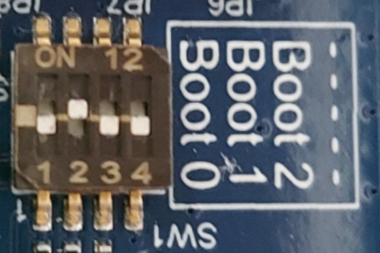
Fig. 94 stm32mp15-ev1 eMMC boot
- Reset the board to boot the installed LmP image.