i.MX 8MMini Evaluation Kit with SE050ARD
This document will walk a developer through the steps of installing a
FoundriesFactory image with the SE050 hardware enabled onto the NXP
imx8mmevk that is connected to the NXP OM-SE050ARD development platform.
Note
An image created in the factory with the SE050 enabled will not boot on boards without the SE050 properly attached.
Attaching the SE050
Using four male to male jumper wires (Arduino Compatible Pin size) connect the two boards as follows:
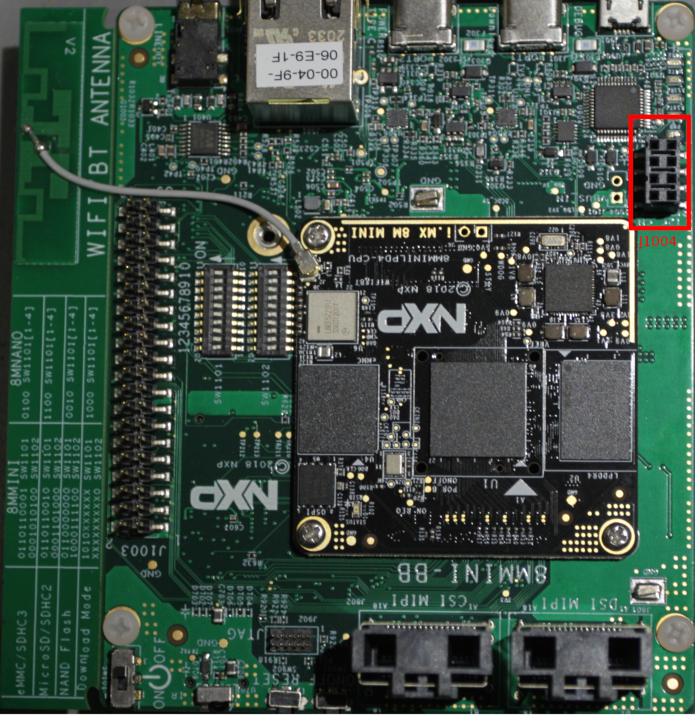
Fig. 22 imx8mmevk
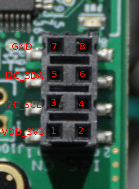
Fig. 23 imx8mmevk i2c pinout
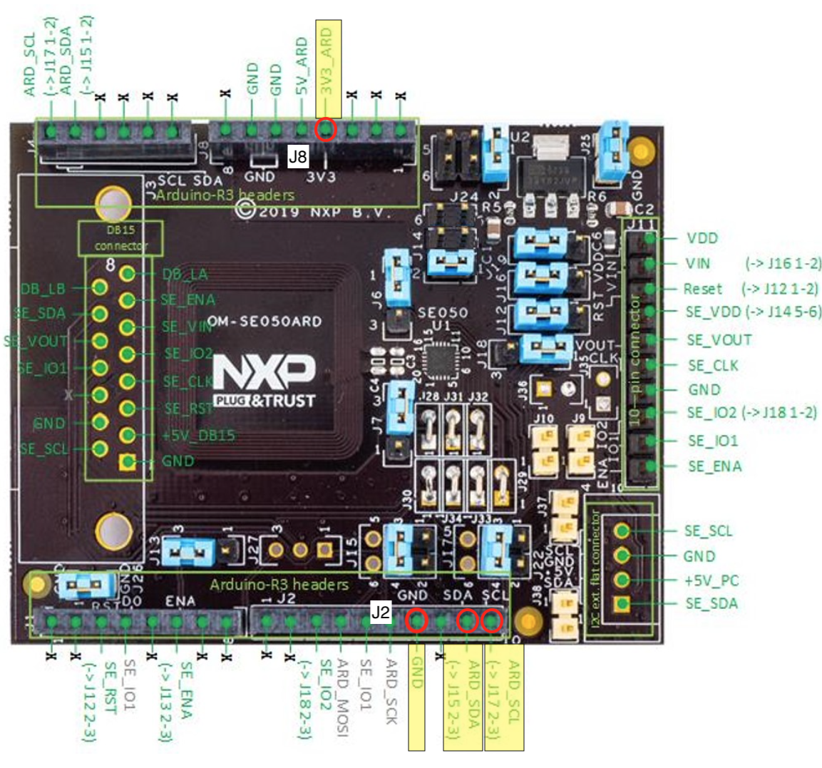
Fig. 24 SE050ARD
Connect the signals as follows:
| Signal | imx8mmevk | OM-SE050ARD |
|---|---|---|
| SCL | J1004 pin 3 | J2 pin 10 |
| SDA | J1004 pin 5 | J2 pin 9 |
| VDD_3V3 | J1004 pin 1 | J8 pin 4 |
| GND | J1004 pin 7 | J2 pin 7 |
Alternatively use J22 on OM-SE050ARD and connect as follows
| Signal | imx8mmevk | OM-SE050ARD |
|---|---|---|
| SCL | J1004 pin 3 | J22 pin 4 |
| SDA | J1004 pin 5 | J22 pin 1 |
| VDD_3V3 | J1004 pin 1 | J22 pin 2 |
| GND | J1004 pin 7 | J22 pin 3 |
Be sure that the jumpers on the SE050 evaluation board are set as follows:
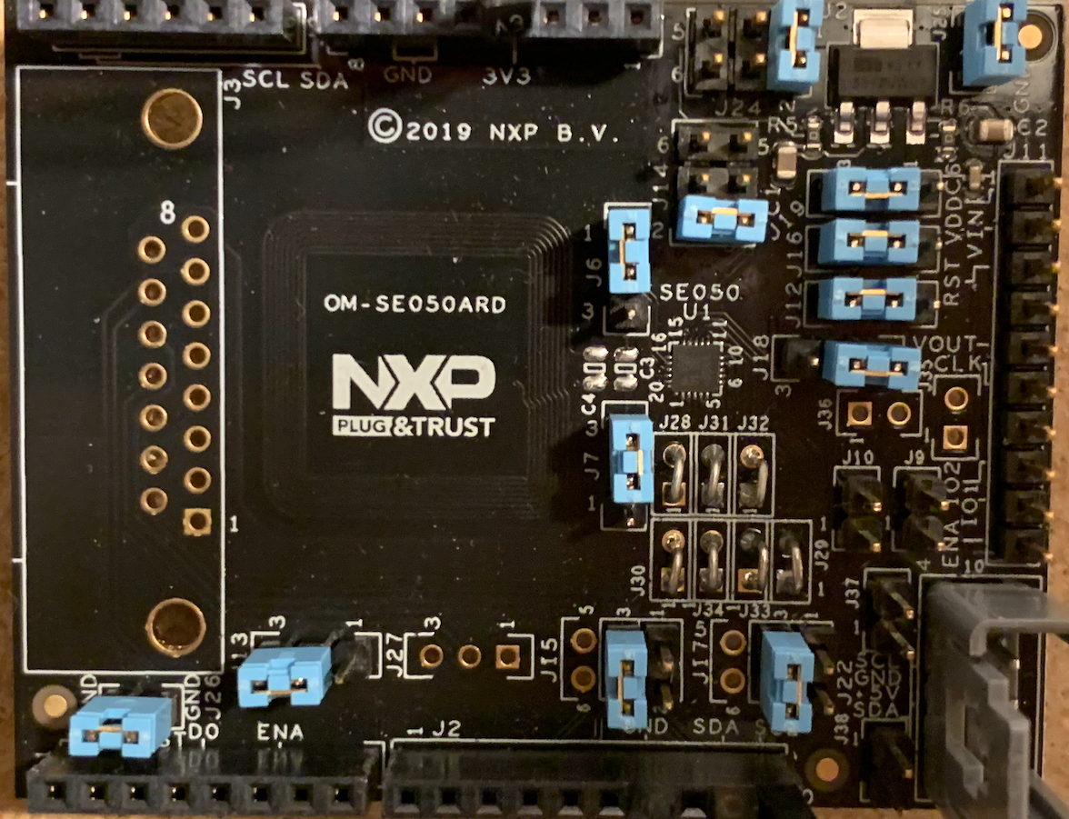
Fig. 25 SE050 Jumper Settings
Lastly the connected boards should look like this:
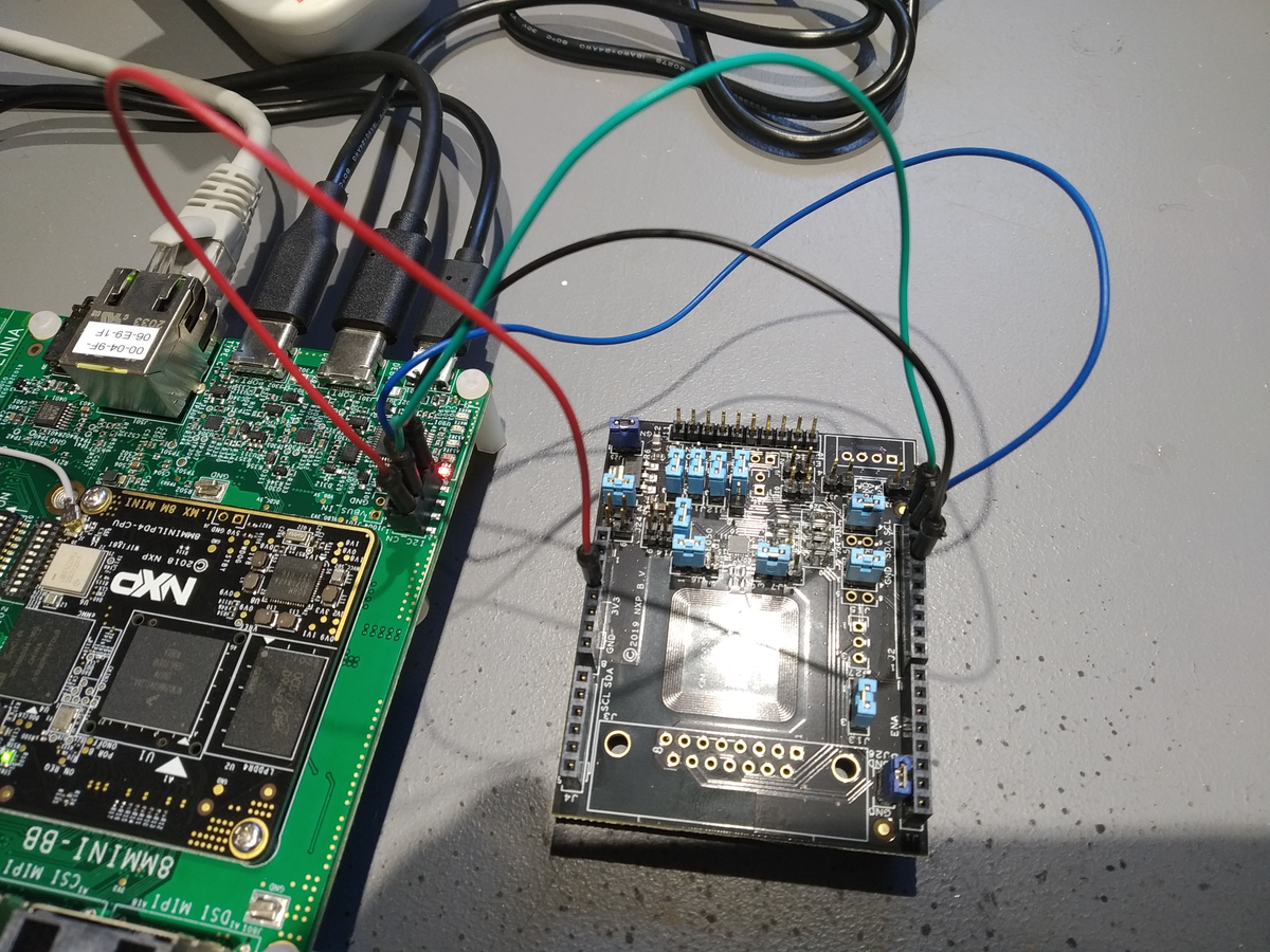
Fig. 26 Wire Connections Between Boards
Installing the FoundriesFactory Image
Download the images that have the SE050 enabled from the factory following the instructions in i.MX 8M Mini Evaluation Kit.
Note
A reference on the needed changes to enable the SE050 middleware can be found in Enabling SE05X.