Apalis iMX6 with the Ixora Carrier Board
Note
The instructions in this section also applies to those boards with secure boot enabled. There are references on how to perform common instructions along with the flow.
The Security Reference Manual details the required background for secure boot.
Preparation
Ensure you replace the <factory> placeholder below with the name of your
Factory.
Download necessary files from
https://app.foundries.io/factories/<factory>/targetsClick the latest Target with the
platform-develTrigger.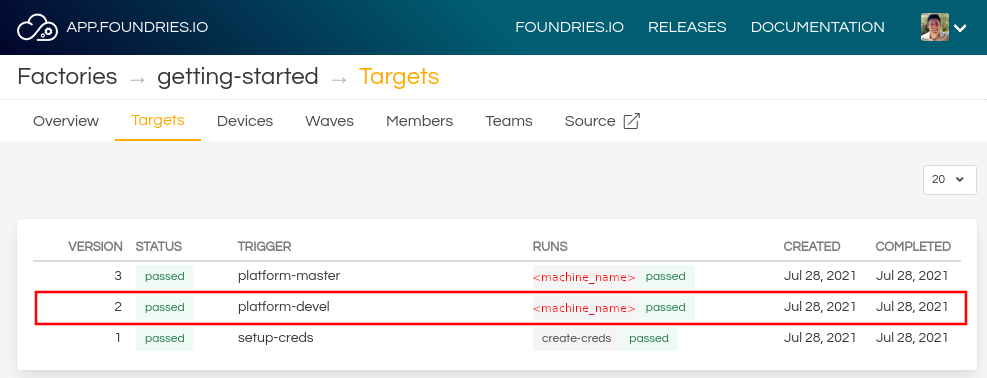
Expand the run in the Runs section which corresponds with the name of the board and download the Factory image for that machine.
E.g:lmp-factory-image-<machine-name>.wic.gzu-boot-<machine-name>.itbsit-<machine-name>.binSPL-<machine-name>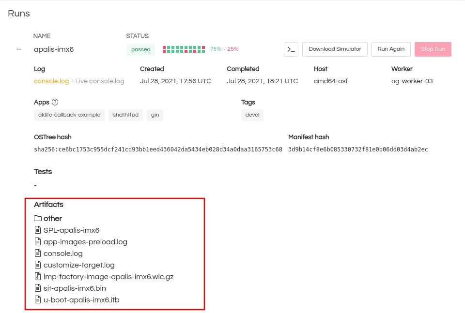
Extract the file
lmp-factory-image-apalis-imx6.wic.gz:gunzip lmp-factory-image-apalis-imx6.wic.gz
Expand the run in the Runs section which corresponds with the name of the board mfgtool-files and download the tools for that machine.
E.g:
mfgtool-files-<machine-name>.tar.gzDownload and extract the file
mfgtool-files-apalis-imx6.tar.gz:tar -zxvf mfgtool-files-apalis-imx6.tar.gz
Organize all the files like the tree below:
├── lmp-factory-image-<machine-name>.wic.gz
├── u-boot-<machine-name>.itb
├── sit-<machine-name>.bin
├── SPL-<machine-name>
└── mfgtool-files-<machine-name>
    ├── bootloader.uuu
    ├── full_image.uuu
    ├── SPL-mfgtool
    ├── u-boot-mfgtool.itb
    ├── uuu
    └── uuu.exe
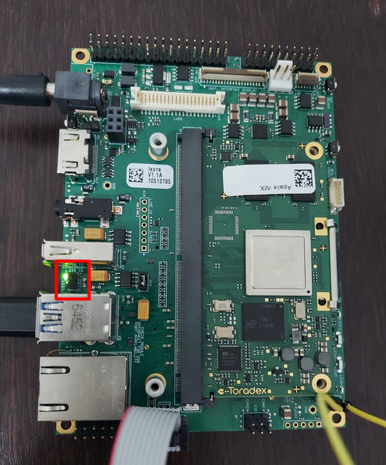
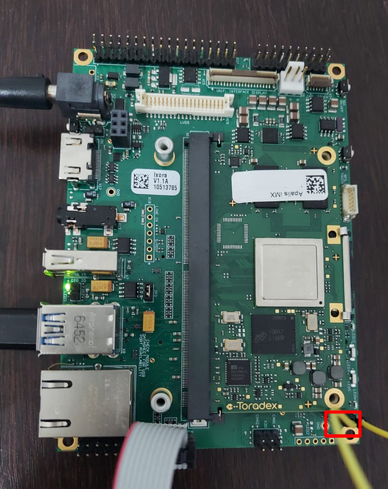
Hardware Preparation
Set up the board for updating using the manufacturing tools:
Ensure that the power is off (SW1)
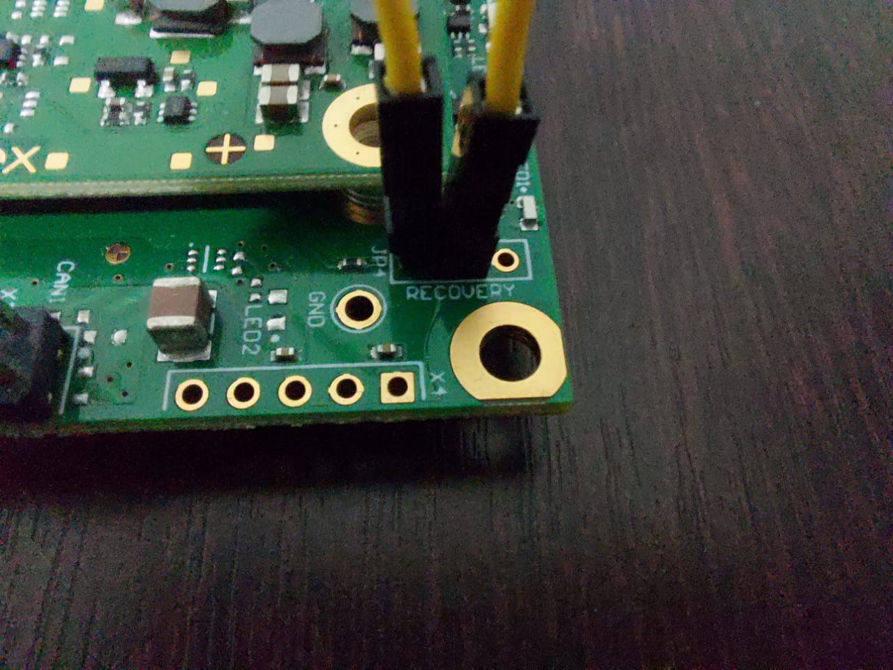
Put the apalis-imx into Recovery Mode:
Power on the board by pressing the SW1 button.
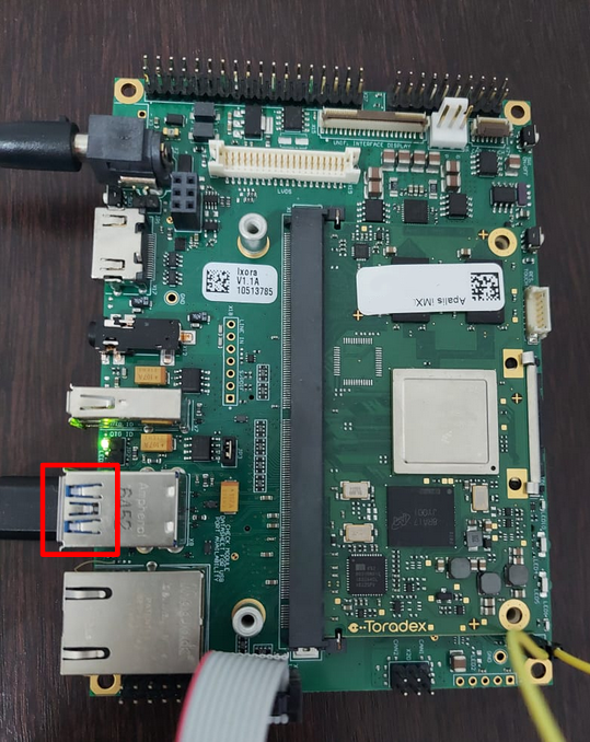
Flashing
Once in serial downloader mode and connected to your PC, the evaluation board should show up as a Freescale USB device.
Note
Device names and IDs can slightly differ from the steps below.
Note
For instructions on how to sign the required images before flashing them to the board with secure boot enabled, follow the instructions from Machines with secure aspects enabled by FoundriesFactory.
Verify target is present:
$ lsusb | grep Freescale
Bus 002 Device 052: ID 15a2:0080 Freescale Semiconductor, Inc.
In this mode you will use the
uuutools to program the images to the eMMC.Run the command below to program the LmP to the EMMC:
$ sudo mfgtool-files-<machine-name>/uuu -pp 1 mfgtool-files-<machine-name>/full_image.uuu
uuu (Universal Update Utility) for nxp imx chips -- libuuu_1.4.43-0-ga9c099a

Success 1    Failure 0


1:31     3/ 3 [=================100%=================] SDPV: jump
2:31     8/ 8 [Done                                  ] FB: done
Turn off the power.
Put the board into run mode
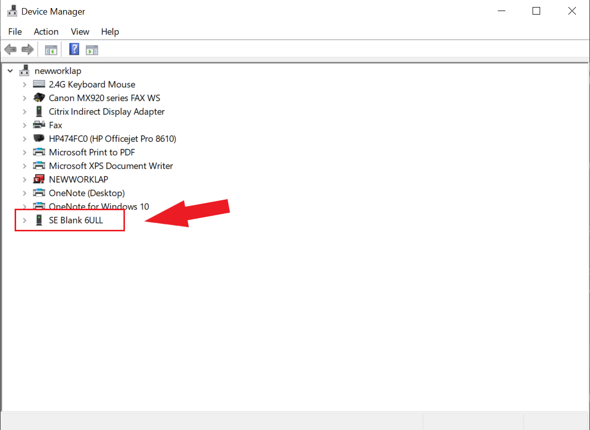
- Start the
Device Manager - Select
View - Select
Devices by container - Verify a device like the following:
Run the command below to program the LmP to the EMMC:
C:\Users\Someone> mfgtool-files-<machine-name>\uuu.exe -pp 1 mfgtool-files-<machine-name>\full_image.uuu
uuu (Universal Update Utility) for nxp imx chips -- libuuu_1.4.43-0-ga9c099a

Success 1    Failure 0


1:31     3/ 3 [=================100%=================] SDPV: jump
2:31     8/ 8 [Done                                  ] FB: done
Turn off the power.
Put the board into run mode
To go back to run mode, disconnect the jumper from the recovery pads (JP4) and reconnect the JP2 jumper.
Power on the board to boot the new image.